1.Basic Introduction
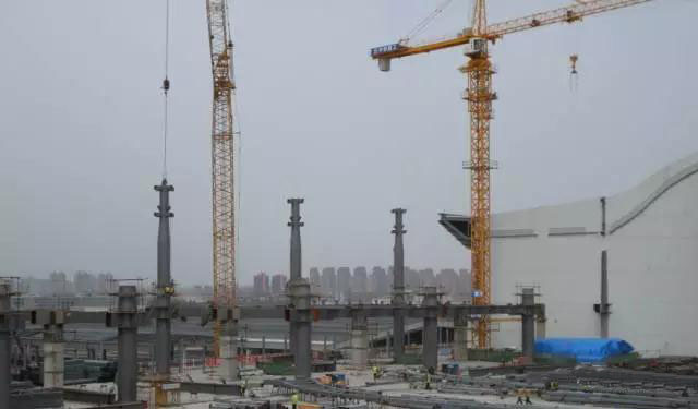
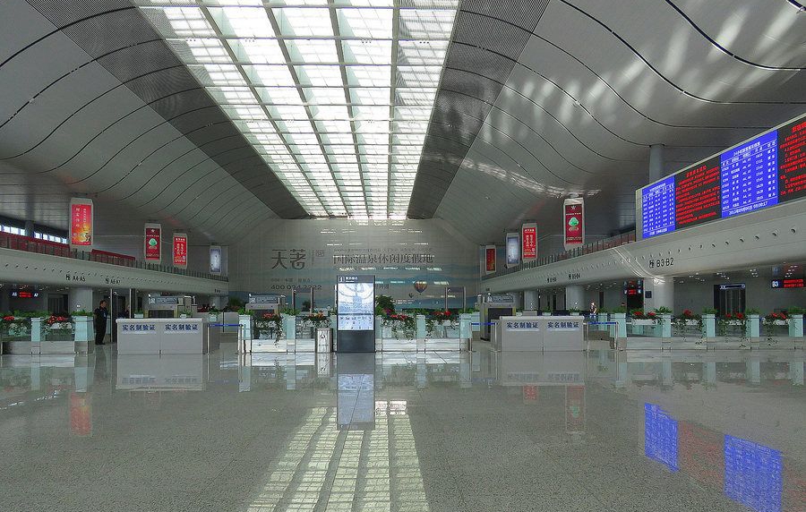
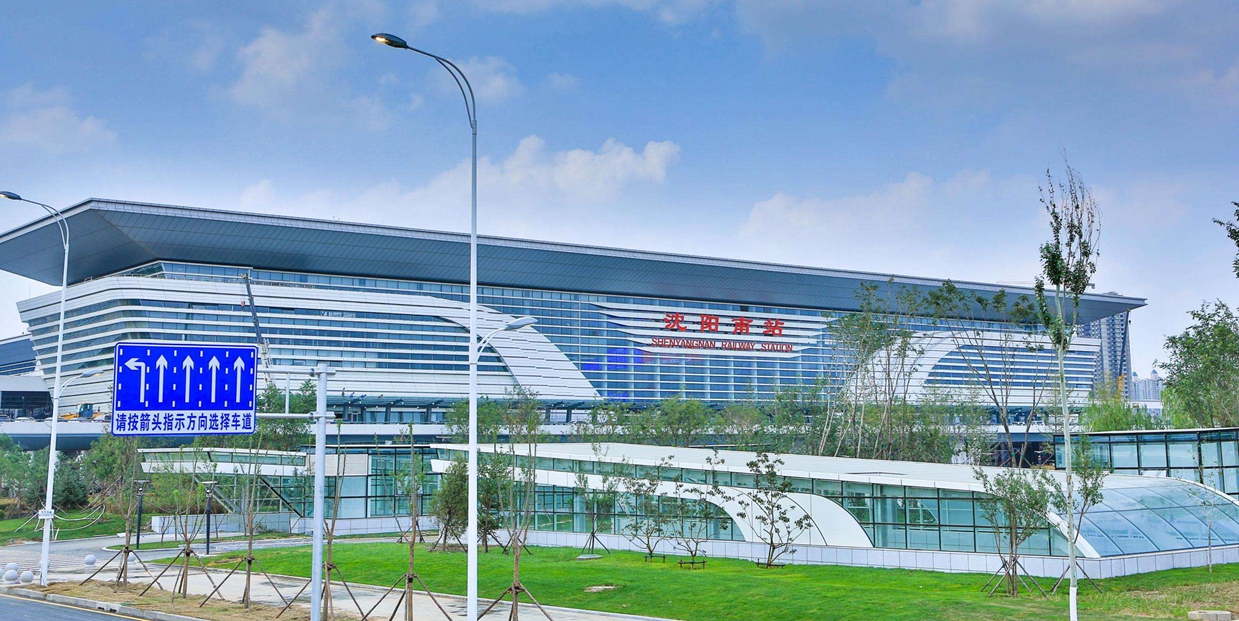
Shenyang South Train Station adopt steel structure, the length of the steel truss is 286.5m, and the span of the roof truss is 21m+66m+21m, and the overhang of the eave is 8.0m. The basic column grid is 10.5m*21.5m, 10.5m*24m. The height of the elevated story is 8.745m, the height of the mezzanine is 16.4m, the height of the roof is 29.91-37.51m.
(Contact us if you need we to do the design for you.)

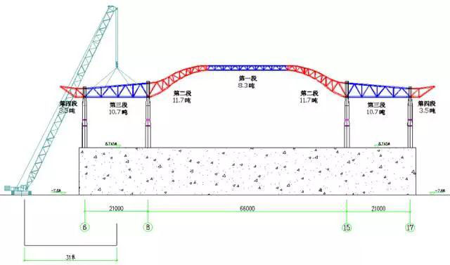
The span between columns of axis 8-15, the weight of the steel parts of this section is 31.7 tons, the height of the arch roof truss is 9.45m. Please check the drawings under below.
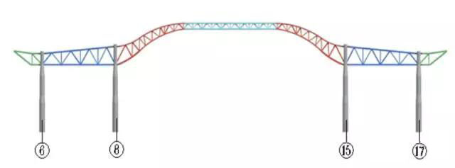
Pic 2 The sketch drawing of the partitioned roof truss.
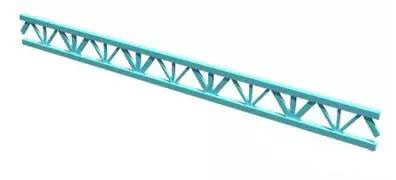
Pic 3 The weight of part 1 is 8.3 tons.

Pic 4 The weight of part 2 is 11.7 tons.

Pic 5 The weight of part 3 is 10.7 tons.

Pic 6 The weight of part 2 is 3.5 tons.
There are two solutions for the roof truss installation, each solution has its own advantages and disadvantages.
Solution 1: Partitioned steel truss hoisting
Advantages:
a.There are enough space for the assemble work under the roof truss, this solution assure the work will be done on schedule;
b.There will be slightly influence to the underneath concrete floor;
c.The support frame can be cycled use, it won’t need a large quantity, will save a lot invest;
d.There is a small change of internal force of the member bar, during the assembly;
Disadvantages:
a. Need supper power hoisting machinery, charge expensive;
b. A lot of work high above the ground;
Solution 2: Integral elevation
Advantages:
a.You can get high assemble quality of the roof truss;
b.Less work high above the ground
Disadvantages:
a.The truss assemble need to after the concrete floor on the elevation of 9m have enough strength, it can be done ahead of the schedule, it’s harm to the construction period;
b.The construction of the floor needs a lot of workspaces, and it’s hard to proceed the other work at the same time;
c.The height of the arch truss is too high, need to use a lot of support frame until finished the assemble;
d.There is big change of internal force during the assembly;
Solution decide:
Considering the limited construction period, and better change of the internal force of the member bar, save more invest, after comprehensive comparison, we decide to use solution 1 which is partitioned hoisting. The truss between axis 8 to 15 can be partitioned to 3 parts, and we need to set some temporary support frame because there are no support columns under the parts.
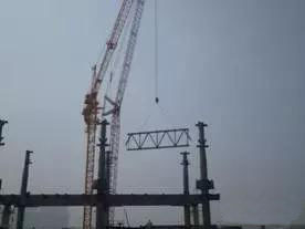
We are going to use a 400 tons crawler crane to lift the columns, beams and the transverse & longitudinal truss between axis 6 – 8 and 15 – 17, when finished the assembly of this section, then hoisting the horizontal & vertical sub truss and the overhang units.
3.Plan checking and implementation
3.1 The plan checking and implementation of the central steel roof truss
3.1.1 Steel structure parts hoisting checking
(1) The performance of the 400tons capacity crawler crane CC2400-1
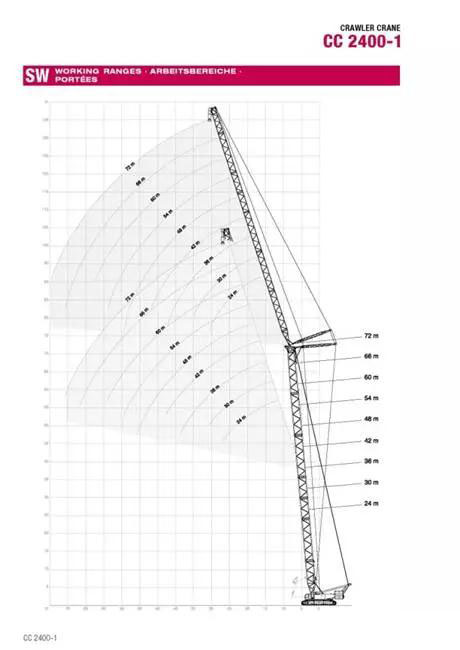
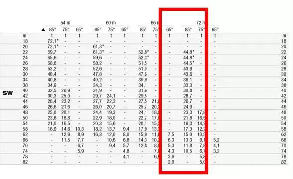
Pic 7 The performance of the 48m main jib and the 72m fly jib
(2)Steel columns hoisting checking
The section of the concrete columns below 16.28m under the elevated mezzanine is P1600*35, the section of the steel columns above 16.28m is P1400*35, according to the characteristics of the distribution of steel columns and the performance of the crane, divided the column into two parts, the divided point is 18.5m.
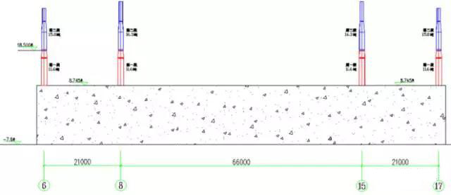
Pic 8 The sketch of partitioned column
Analyse the hoisting performance of the second part of the middle column which has the highest hoisting requirements, it can meet the requirements.
(3)The main truss hoisting checking
The main steel truss needs 2 400 tons crawler crane work together, hoisting from two sides. The truss can be divided into 7 parts, the 66m span truss can be divided into 3 parts, and both two sides can be divided into 2 parts. (pic 9)
Pic 9 The sketch map shows the partition of the main truss and the sub truss
Pic 10 Performance analysis of hoisting the first section
Table 1
Pic 11 Performance analysis of hoisting the second section
Table 2
Pic 12 Performance analysis of hoisting the third section
Table 3
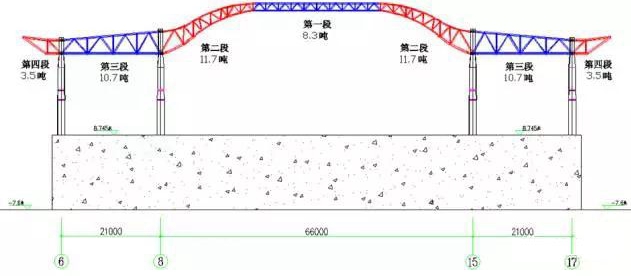
Pic 9 The sketch map shows the partition of the main truss and the sub truss
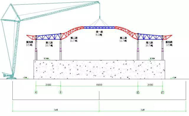
Pic 10 Performance analysis of hoisting the first section
| The weight of steel components | Performance of the crane | Meet the requirements | |||
| Length of crane beam | Working radius | Weight of hook | Permit hoisting | ||
| 8.3t | 48m+72m | 74m | 0.5t | 10.5t | Yes |
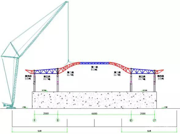
Pic 11 Performance analysis of hoisting the second section
| The weight of steel components | Performance of the crane | Meet the requirements | |||
| Length of crane beam | Working radius | Weight of hook | Permit hoisting | ||
| 8.3t | 48m+72m | 74m | 0.5t | 10.5t | Yes |
Pic 12 Performance analysis of hoisting the third section
| The weight of steel components | Performance of the crane | Meet the requirements | |||
| Length of crane beam | Working radius | Weight of hook | Permit hoisting | ||
| 8.3t | 48m+72m | 74m | 0.5t | 10.5t | Yes |
3.1.2 Analyse the construction process and the implementation of the solution
(1) The simulation of the force and strain during the construction
The installation of steel structure members takes time, the force of the structure members and the boundary conditions changing all the time during the process. So the maximum force state or the final state of the steel members are big differences from the state of design analysis, due to adopting different construction method or order. For the safety of the steel structure during the construction and after the installation, we need to simulate the construction process and analysis. We use the software MIDAS GEN/8.0 to run the analyze, and we can get the results of force and strain during the construction.
(2)Calculation model
Due to the west & est unit of the central station building have a similar arrangement, so we chose the typical unit(the worst condition) (frame II-axis J to axis K, roof truss II- axis J to K) to run the simulation.
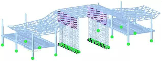
Pic 13 MIDAS model of the construction
Structural unit
Concrete filled steel tubular column use SRC material and structure, bracing web member use truss unit, the other unit adopt beam simulation.
Loading Condition
According to the solid model, gravity rate use 1.0.
A load of purlin and purlin bracing load onto the upper bar of the truss, the equivalent load is 1.53KN/m.
The weight of the skylight load onto the upper bar of the truss, the equivalent load is 5.0KN/m.
Board conditions.
The steel pipe filled with concrete use a rigid connection.
The bottom of the bracing frame adopt hinge joint, without considering the advantages of the bottom reinforcement measurements; release the Y, Z and corner restraint of the top bracing frame.(Pic 14)
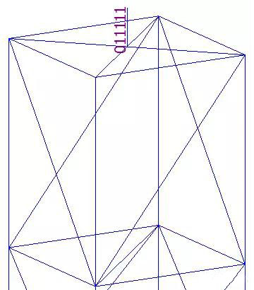
Pic 14 release the top restraint of the bracing frame
(3)The construction process analyze and the implementation of the solution
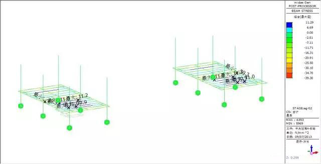
Step one, hoisting the concrete-filled steel tube columns and beams.
Force analyze: simulate and analyze the force, the max force of the beam is 39.3Mpa, meet the requirements.
Step two, assemble the roof truss, form the stable framework.
Force and transformation analyze: max vertical transformation 13.1mm, appears in the beam, nearly no transformation to the truss, max force of the bar member is 38.72MPa.


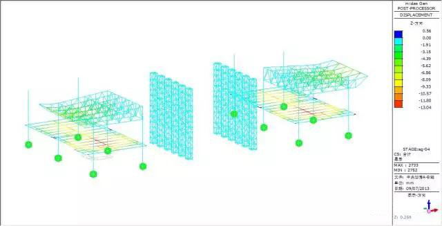
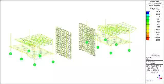
Step three, assemble the sub-roof truss, form the integrate; set bracing at the height of 8.745m.
Force and transformation analyze: max vertical transformation 13.04mm, appear at the beam, the vertical transformation of the truss is small, the max force inside of the bar member is 38.23MPa.
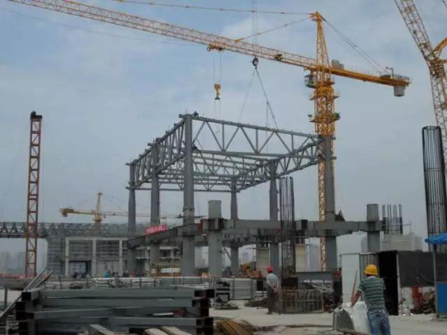
Step four, install the middle roof truss segment II.
Force and transformation analyze: max vertical transformation 13.05mm, appear at the beam, small vertical transformation; max internal force 38.53MPa.
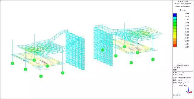
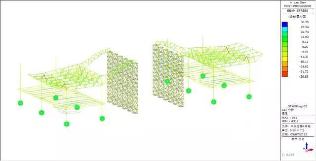
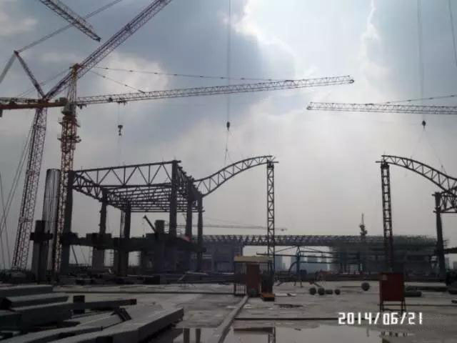
Step five, install the middle roof truss segment I.
Force and transformation analyze: max vertical transformation 13.05mm, appear at the beam, small vertical transformation; max internal force 38.49MPa.
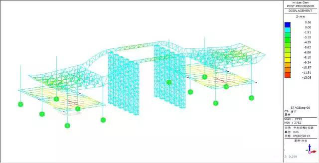
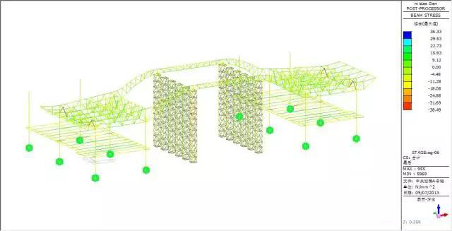
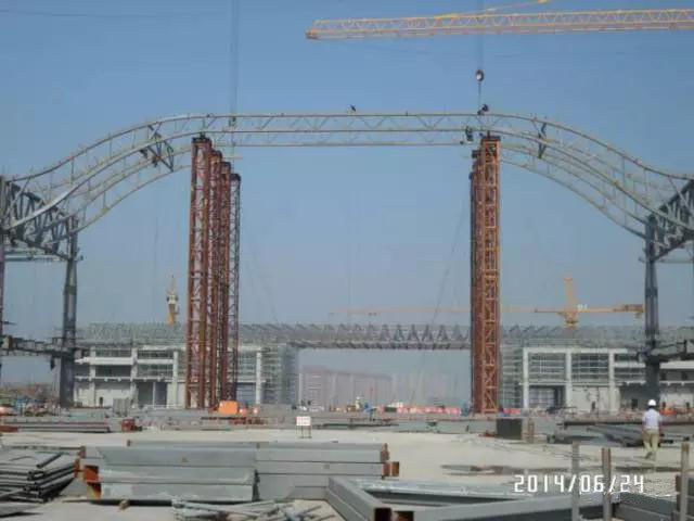
Step 6, install the lateral sub truss in the middle of the roof.
Force and transformation analyze: max vertical transformation 13.04mm, appear at the beam, small vertical transformation; max internal force 38.51MPa.
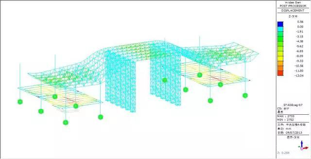
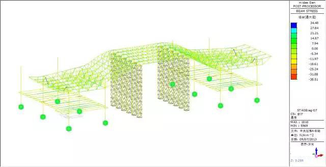
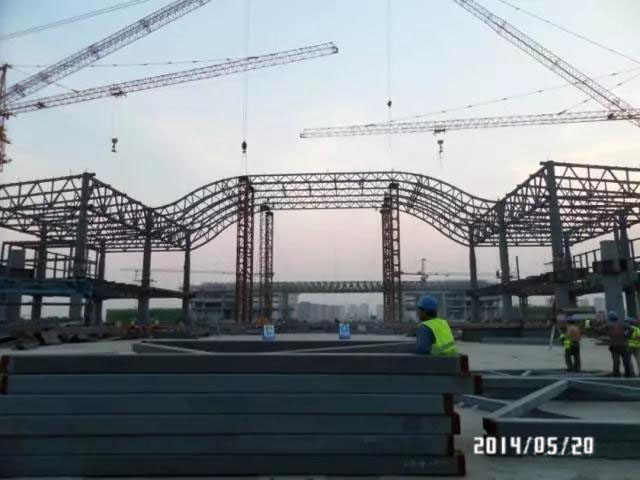
Step 7, install the longitudinal sub truss in the middle of the roof.
Force and transformation analyze: max vertical transformation 13.04mm, appear at the beam, small vertical transformation; max internal force 38.5MPa.


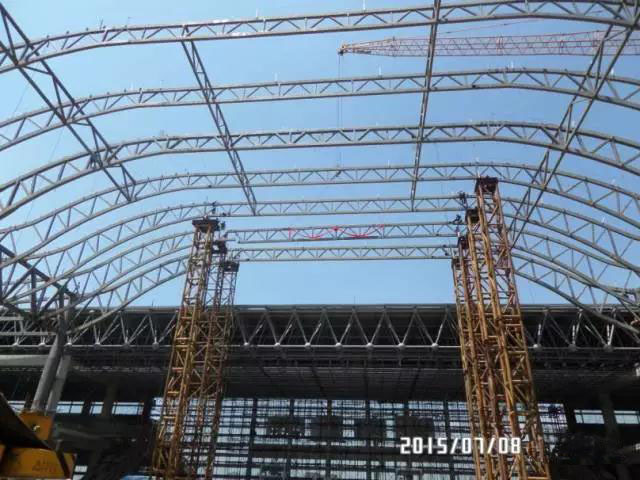
Step 8 release the restraint of the roof, tear down the bracing frame.
Force and transformation analyze: max vertical transformation 27.2mm; max internal force 48.2MPa.
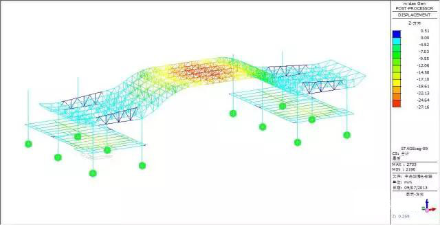
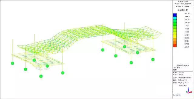
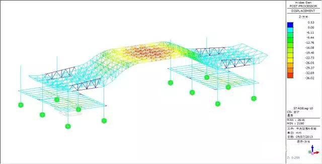
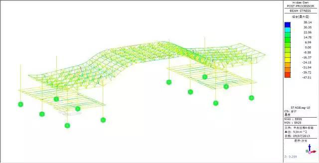
Step 9 install the purlin, skylight.
Force and transformation analyze: max vertical transformation 36mm; max internal force 47.51MPa.
4.Conclusion
(1)In this project, the span of the roof truss is 66m, it’s a big span, we hoisting partitioned, and assemble above the ground, there are 12000ton steel structure parts, it took 4 months to finish the hoisting, finally we meet the schedule.
(2)During the construction of this big span steel structure truss, the max structure transformation is 36mm, the max stress is 45.51MPa, structure transformation and stress meet the requirements of the codes and design. Compare the partitioned hoisting and integral hoisting, the additional transformation is 1.9mm, additional stress is 1.2MPa, they are far from the limits, meet the requirements. So the partitioned hoisting solution is safe and reasonable.
(Original article here)

Leave A Comment